This phase is the response to the necessity of detailing the position of the agents in distributed systems or in mobile-agents contexts.
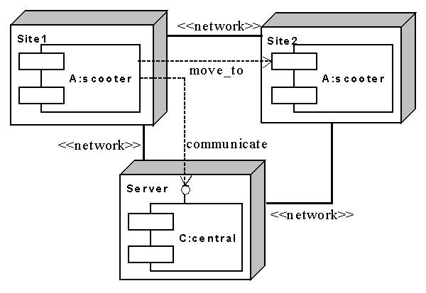
The Deployment Configuration diagram describes where the agents are located and which different elaborating units they need in order to communication with each other. As usual, elaborating units are shown as 3-D boxes (see figure). Agents are shown as components; their names are in the form agent-name: agent-class. Communications between them are represented by dashed lines with the communicate stereotype, directed as in the R.D. diagram. For each communication described in the R.D. diagram, occurring between agents in different elaborating units, a dashed line is drawn. The receiving agent has an interface to show that it is capable of dealing with that communication (i.e., it understands the protocol used). An extension of the UML syntax is used in order to deal with mobile agents moving from one computer to another. A dashed line with the move_to stereotype represents it (see figure).
An example of Deployment Configuration diagram. The scooter agent moves from one node to another
In this diagram it is also possible to specify the hardware devices used by the agents (sensors and effectors) and the modes of communication among agents in different elaborating units (e.g., traditional/wireless networks). If two agents in different elaboration nodes need to communicate (as stated in the previous phases of the design), a path of connection should be provided between the two nodes.
These constraints about the connections could also be dynamic. In fact, if agent A needs to communicate with agent C, but moves across the network (see figure), we need to introduce the connection constraints as dependent on agent A's position. Therefore, we introduce an OCL constraint in all the needed connections for this specific purpose.
Next phase: none
Previous phase: Code Completion Baseline
Home: PASSI homepage